Path Analysis
With Forward Path Analysis, users gain Google-like search capabilities for their network, providing instant and interactive visibility into all end-to-end traffic behaviors. Each search result not only indicates where the traffic can flow but also includes the relevant configuration and state details that explain how the traffic is processed.
All information is presented in a vendor-agnostic format, allowing users to understand every transformation occurring at each hop in the path without requiring expertise in vendor-specific platforms. At the same time, users can drill down into the precise vendor-specific configuration responsible for each transformation when deeper analysis is needed.
Quick Path Analysis
With Quick Path Analysis the user enters very clear fields: traffic source, traffic destination, and
optionally traffic type (tcp, udp, icmp, etc.). This enables users new to the Forward Enterprise platform to
immediately and intuitively start leveraging the Path Analysis capabilities.

Advanced Path Analysis Queries
Advanced Forward Enterprise users rely on the Search Bar to type their Search queries. A help string shows a few
examples of text and path searches: 
Pre-built Searches
Once the user clicks on the search bar a help menu appears. The help menu shows a Common Traffic Searches heading
underneath which the system displays the most common search types that are routinely performed by our users.
 If the user selects one of the
options, the system pre-populates the search bar with the relevant search clauses. The user can then input data into
each of the clauses and decide to close or leave blank those that are not needed:
If the user selects one of the
options, the system pre-populates the search bar with the relevant search clauses. The user can then input data into
each of the clauses and decide to close or leave blank those that are not needed:
-
Classic Five-Tuple search The user can input the classic 5-tuple: Source IP (or a network Entry Point), Destination IP, IP Protocol, and Layer-4 Ports

-
Paths for a NAT'd destination For NAT'd flows the destination IP address may change along the path. The user can define pre-NAT and a post-NAT IP addresses to surface the results for this complex yet common network behavior. This example gives the user a glimpse into the flexibility of Forward's Path Analysis by enabling the user to concatenate search clauses and build complex queries into network behaviors.

-
Paths for a specific Layer 3 gateway This case is useful when the search query contains a source subnet or address that could ingress the network from multiple places. By default, Forward applies strict reverse-path forwarding logic to determine the Layer-3 gateway that is the most likely to handle the flow. With this guided search the user can explicitly specify the Layer-3 gateway if needed.

-
Paths bypassing a specific device The user gets another glimpse of the Forward Path Analysis flexibility when this search is selected. In this case the user can define a query that checks for flows bypassing a given device. An example of the usefulness of this search is the one where the network engineer wants to verify whether a specific flow (or any flow) actually bypasses a firewall.

-
Paths to a load-balanced VIP This search simply shows how the user can specify in the query a VIP address.
 The list will likely grow in the future with
additional common search types.
The list will likely grow in the future with
additional common search types.
Search Keywords
The user can also build its own queries outside the common cases. The user can in fact build them by typing the path and header filters clauses. These are the currently supported keywords.
-
from The from keyword tells the system to look for paths starting at the location specified in the clause. Acceptable inputs are:
- IP address of a discovered host
- Generic IP address not associated to a discovered host
- In this case the system will consider the location(s) where the model expects traffic sourced by this IP address could enter the network. In case of multiple locations, the user can further refine the query by adding an ingress clause to specify the first hop.
- Device
- Device + interface
- Device + VRF
-
to The to keyword tells the system to look for paths ending at the location specified in the clause. Acceptable inputs are:
- IP address of a discovered host
- Generic IP address not associated to a discovered host
- In this case the system will consider the location(s) where the model expects traffic sourced by this IP address could enter the network. In case of multiple locations, the user can further refine the query by adding an egress clause to specify the last hop.
- Device
- Device + interface
- Device + VRF
-
at When the IP address in a from or a to keyword has an ambiguous location, the UI presents the user with a list of possible locations for the IP and the user is asked to select a particular location (device) to ground the query. This generally occurs when we have route based lookups only for the IP address and the IP address has many egress points from the portion of the network that was collected. In such cases, the at keyword is used to denote the location that was selected by the user. The workflow naturally takes the user to results with an at keyword. It is not something the user needs to type in proactively.
-
ingress The ingress keyword tells the system to look for paths ingress-ing the "location" specified in the clause. Acceptable inputs are:
- Device
- Device + interface
- Device + VRF Note: Multiple ingress clauses can be used to drill down to a very specific path
-
egress The egress keyword tells the system to look for paths egress-ing the "location" specified in the clause. Acceptable inputs are:
- Device
- Device + interface
- Device + VRF Note: Multiple egress clauses can be used to drill down to a very specific path
-
through The through keyword specifies a mandatory intermediary device in the path search. Acceptable inputs are:
- Device
- Device + interface
- Device + VRF Note: Multiple through clauses can be used to drill down to a very specific path
-
bypass The bypass keyword tells the system to return paths that bypass a specifies intermediary device. Acceptable inputs are:
- Device
- Device + interface
- Device + VRF Note: Multiple bypass clauses can be used to drill down to a very specific path
-
status Describes the overall end result of the traffic flow. Acceptable inputs are:
- Delivered - A flow that is successfully delivered across the network.
- Dropped - Explicitly dropped by a rule (firewall, ACL, etc.) within the network.
- Loop - A flow that traverses the same node/interface/VRF more than once in a Layer 2 or a Layer 3 loop.
- Blackhole - Implicitly dropped due to the lack of a matching/default rule.
Let’s look more deeply into the status codes, and how they related to the outcomes of a search:
- Delivered This takes into account a complete scope of the search query, including source and destination IP and/or MAC address, source and destination device along with ingress or egress interface, etc. Adding the “Delivered” status code turns an open-ended search query into a closed ended one, and confirms the network’s ability to successfully deliver traffic per the specified search query. A “Delivered” status code would signify that the search query has found one or more paths in the network that either egress the edge interface on the final destination device, or is consumed by the device itself.

-
Dropped An outcome of Dropped means that the network element drops the packet because of an explicitly or implicitly configured rule. This could be a firewall rule or an ACL on routers, switches and their corresponding interfaces. The path that results in the “Dropped” status can happen on the ingress interface of the device or on the egress, depending on the configuration and the individual processing characteristics of the device.
-
Loop The Forward Platform is able to analyze packets as they would traverse network elements. Forward infers that if a packet should traverse the same interface or VRF more than once without any changes to the packet header, it would be “looping” and would display the status as a Loop.
-
Blackholed This outcome is where traffic flows get implicitly dropped due to the Forward Networks platform not being able to match any forwarding rule or behavior in the network. It is uncommon in practice and in well-formed networks to experience a blackholed outcome, therefore additional scrutiny should be given. An example would be if there is no default route in the routing table and the Forward platform cannot determine a way to match traffic to any IP routes for a corresponding VRF.
-
Inadmissible It means that the traffic was not admitted into the network. This happens when the first hop interface does not accept the traffic, e.g. incoming traffic had a vlan tag 10 while the ingress interface is an access interface that only permits traffic with vlan tag 20.
-
Unreachable An unreachable outcome means that an ARP/NDP resolution failed along the path resulting in traffic not getting delivered to the intended destination.
Here an example of a "complex" query that utilizes all the above keywords:

Layer2-4 Header Filters
When performing Path Analysis for a specific application flow, the user can leverage packet header filters to pinpoint
the specific set of paths that are responsible in delivering the application. The system tries to guess which header the
user is trying to input and provides a suggestion. For example, entering "10.1.1.1" will be associated with a Source
or Destination IP address.  The user can specify the
following header types at each hop if needed to account for header transformations like NAT:
The user can specify the
following header types at each hop if needed to account for header transformations like NAT:
- dest-ip
- source-ip
- l4-dest-port
- l4-source-port
- dest-mac
- source-mac
- ethernet-type
- vlan-id
- ip-protocol
- vni (Virtual Network Instance)
- tcp-flags
- route-target
- sgt (Secure Group Tagging)
Layer 7 Filters
Next-generation firewalls (NGFW) offer more advanced capabilities than traditional firewalls, resulting in increased security. They can filter packets based on the layer 7 of the OSI model, in fact the user can configure policies based on application (app-id), url, user-id and user-group. Forward supports path analysis queries that include these layer7 filters.

Layer 7 filters can only be used in association with the from clause.
The release 22.7 has introduced the ability for the Org Admin to set system-wide fixed defaults to be used in layer 7 path analysis. The user should familiarize with these settings before starting to issue path queries that include layer 7 filters.
APP-ID By default, the system treats the app-id field as wildcarded for the path query unless the query explicitly specifies a value for app-id. This behavior is useful when the user wishes to explore matching paths with all possible app-id values. The filters' panel would enumerate any app-ids seen in firewall rules traversed by the matching traffic and by selecting one or more of them the user can further investigate behaviors for specific app-ids. It is recommended to keep this system setting for users that are interested in analysing the behavior of app-id policies. Additionally, the system will soon map automatically any well-known L4 port provided by the user to the corresponding app-id.
- Disabling App-Id matching - The Org admin can globally turn off app-id matching by enabling its system default
to
unidentified(go to Settings > System > Org Preferences > Traffic Defaults). When app-id is set tounindetified, the system bypasses firewall policies that include app-id matches. This could be useful when the user is not fully aware or interested in any specific app-id. Bypassing app-id means ignoring any app-id policies on firewalls and falling through to lower priority rules that do not have app-id matches (possibly shadowed rules). If the firewall only permits traffic to specific app-ids, then query results will include only drops or blackholes.
URL By default, the system internally sets the URL query field to none and bypasses firewall policies that
include URL matches. The assumption is that the average user is not fully aware nor interested in specific URL-based
analysis. Bypassing URLs means ignoring any URL-based policies on firewalls and falling through to lower priority rules
that do not have URL matches (possibly shadowed rules). If the firewall only permits traffic to specific URLs, then
query results will include only drops or blackholes. Users interested in analysing the behavior of URL-based policies
should turn this default setting off as indicated just below.
- Enabling URL matching - The Org admin can globally turn on URL matching by disabling the system default (go to Settings > System > Org Preferences > Traffic Defaults). When that happens, the system starts treating the URL field as wildcarded for the path query unless the query explicitly specifies a value for URL. This setting is useful when the user wishes to explore behaviors for all possible URLs. The filters' panel would enumerate the URLs seen in firewall rules traversed by matching traffic and they can be selected to further investigate behaviors for specific URLs.
Learn more about URL matching in this dedicated page.
USER-ID/GROUP By default, the system treats the user-id/group field as wildcarded for the path query unless the query explicitly specifies a value for them. This setting is useful when the user wishes to explore behaviors for all possible user-id/groups values including unidentified user-id/groups. The filters' panel would enumerate any user-ids/groups seen in firewall rules traversed by matching traffic and by selecting one or more of them the user can further investigate behaviors for specific user-ids/groups. It is recommended to keep this system setting for users that are interested in analysing the behavior of user-ids/groups policies.
- Disabling user-id/group matching - The Org admin can globally turn off user-id/group matching by enabling the
system default to
unidentified(go to Settings > System > Org Preferences > Traffic Defaults). When user-id/group isunindetified, the system bypasses firewall policies that include user-id/group matches. This could be useful when the user is not fully aware or interested in any specific user-id/group. Bypassing user-id/group means ignoring any user-id/group policies on firewalls and falling through to lower priority rules that do not have user-id/group matches (possibly shadowed rules). If the firewall only permits traffic to specific app-ids, then query results will include only drops or blackholes.
Learn more about user-id/group matching in this dedicated page.
IP ToS By default, the system treats the IPToS field as wildcarded for the path query unless the query explicitly specifies a value for it. This setting is useful when the user wishes to explore behaviors for all possible IPToS values. The filters' panel would enumerate any IPToS values seen in firewall rules traversed by matching traffic and by selecting one or more of them the user can further investigate network behaviors for specific IPToS values. It is recommended to keep this system setting for users that are interested in analysing the behavior of policies that include IPToS.
- Disabling IPToS matching - The Org admin can globally turn off IPToS matching by enabling its system default to
0x0(go to Settings > System > Org Preferences > Traffic Defaults). When IPToS is set to0x0, the system will not match firewall policies that include IPToS matches. Usually these policies match on specific non-zero IP ToS values. This could be useful when the user is not fully aware or interested in any specific IPToS value.
LAYER4 SOURCE PORT By default, the system treats the L4 Source Port field as wildcarded for the path query unless the query explicitly specifies a value for it. This setting is useful when the user wishes to explore behaviors for all possible IPToS values. The filters' panel would enumerate any L4 Source Port values seen in firewall rules traversed by matching traffic; by selecting one or more of them the user can further investigate network behaviors for specific L4 Source Port values.
- Using an Ephemeral L4 Source Port - The Org admin can globally enable the default usage of ephemeral L4 source
ports. This is done by enabling the corresponding system default to
65000(go to Settings > System > Org Preferences > Traffic Defaults). When the L4 source port is set to65000, the system will not match firewall policies that include L4 source ports matches. Usually these policies match on specific values smaller than1024.
Even when enabled, these defaults are overwritten any time the user provides an alternative value in the search query. The user-provided value overwrites its default value.
Live DNS Resolution
Forward Enterprise supports live DNS resolution for URLs and hosts.
For instance, to resolve a URL, type the URL in the search bar and select the url with resolved IP suggestion:

Then, select the suggestion with the resolved IP:

Both dest-ip and url filters are added to the query in the search bar:

To resolve a host, type the hostname in the search bar and select the host at resolved IP suggestion:

The DNS resolution is supported in all deployments types. In SaaS deployments, the resolution only supports public DNS entries. In future releases, these deployment types will benefit from the resolution been done from the Forward Collector instead, allowing resolution of private DNS entries as well.
Multicast Path Analysis
Forward Enterprise provides a multicast experience centered around multicast groups and their sources, receivers, and rendezvous points.
It allows you to search for multicast groups and related information using the Search application.
Moreover, it provides multicast ASM and SSM data and control plane modeling to compute complete (*,G) and (S,G) trees, and show them in the Forward Enterprise topology along with the tree's details. This computation can show both currently active tree, as well as the maximum tree that can be formed (potential tree).
Start by typing a multicast group on the search bar.

The Search card will show the Multicast groups and any related rendezvous point configured for that group.
Clicking on the multicast group, the multicast group card will show a list with the count of Active sources, Active receivers, and Rendezvous points for the given multicast group.

- Active sources: multicast sources configured for the given multicast group
- Active receivers: multicast receivers active at the time of Snapshot collection
This information is extracted from IGMP explicit tracking which needs to be enabled on (at least) the edge switch of the subscribers.
- Rendezvous points: rendezvous points configured for the given multicast group
You will see a table with all the details by clicking on any of the above categories. For instance, clicking on Active sources you will see a table with the Source IP address, the Designated router (first router that serves that source), inbound interface, any RP IP address, RP device, RP VRF, and Location of the source.

On the right side of any active sources you can find four icons:
-
Locate on ASM (S,G) tree: it provides a graphical visualization of the ASM (S,G) tree. Use the drop-down menu on the upper right to select one of the following visualization options:
- Active tree only: it includes paths with active subscribers at the time of network collection
- Include potential tree: it includes paths with active subscribers as well as paths that don't have active subscribers at the time of network collection but can potentially serve new subscribers
- Include all devices: shows all devices in the networks. It's useful to understand where the (S,G) tree fits in the context of the full network.
The screenshot below shows an example of a (S,G) tree with active and potential receivers.

-
Locate on SSM (S,G) tree: it provides a graphical visualization of the SSM (S,G) tree, with the same visualization options as the ASM (S,G) tree
-
Locate on (*,G) tree: it provides a graphical visualization of the (*,G) tree, with the same visualization options as the ASM (S,G) tree
-
View Config: provides the source device config and state related to that multicast group

The (S,G) and (*,G) trees displayed by Forward are layer 3 multicast topology.
Exploring Path Analysis Results
Select one of the paths to explore its details: 
Paths
The Forward platform provides the ability to clearly understand how a particular flow traverses through a network
device. The user can zoom in at each hop and see the transformations that a packet goes through across the different
network functions implemented by the network device. This ability becomes extremely useful when trying to troubleshoot a
problem, and it can help the user to more easily understand and learn about network behaviors.
 After entering a search criteria, there could be one
or more paths that satisfy the search. A path is defined as a unique sequence of hops through the network. A hop can be
a layer 2 hop, a layer 3 hop, an MPLS hop, or something similar. One of the most common reasons for multiple paths is
equal-cost multi-path (ECMP), caused when an IGP routing protocol has equal metrics across multiple different links in
the network. Simply click on one of the hops on a path to examine it in detail.
After entering a search criteria, there could be one
or more paths that satisfy the search. A path is defined as a unique sequence of hops through the network. A hop can be
a layer 2 hop, a layer 3 hop, an MPLS hop, or something similar. One of the most common reasons for multiple paths is
equal-cost multi-path (ECMP), caused when an IGP routing protocol has equal metrics across multiple different links in
the network. Simply click on one of the hops on a path to examine it in detail.
If parsing some state or configuration fails in one or more devices in the path, the devices are highlighted with a different color and details of what has failed and what is not reliable on those devices with parsing failure is provided, like in the example below:

The hops in the paths are grouped by locations in the new location-based topology view. To learn more about location based topology, refer to the On-Prem topology page.

Security Mode
When Security mode is enabled, only hops relevant to security—such as ingress and egress Layer 3 hops, and hops that enforce security policies or perform address translation—are displayed. This mode helps security engineers focus exclusively on the hops that are relevant to their analysis.
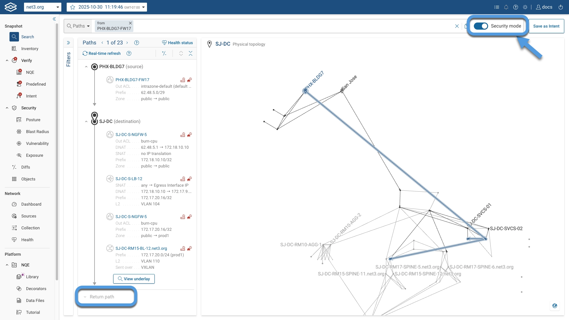
The Return path and Path Diffs features also support Security mode.
Path Groups Ranking Criteria
Each path group includes paths that have similar forwarding behaviors, possibly through different hops e.g. for ECMP.
The path groups returned for a given query are ranked using the following criteria:
- First prefer a path group with longer flow length
- Then prefer a path group based on its Outcome
- First prefer a path group by its forwarding-related Outcome in the following order
- DELIVERED
- DROPPED
- LOOP
- INADMISSIBLE
- BLACKHOLE
- UNREACHABLE
- Then prefer a path group by its security-related Outcome in the following order
- PERMITTED
- DENIED
- First prefer a path group by its forwarding-related Outcome in the following order
- Then prefer a path group not destined to self port
- Then prefer a path group with fewer ACL drop hops (i.e. security-related outcome is DENIED for both path groups, but
one has
denyrules at fewer hops).
Sample Packet
 In the top of the Hop Details card, a drop-down
triangle reveals a sample packet. This view shows how the packet(s) will be transformed by this specific hop. Any text
in green shows header information that was rewritten by the behavior of this hop in comparison to the previous hop. This
per-hop behavior makes it easy to understand complex transformations such as NAT on firewalls and load balancers.
In the top of the Hop Details card, a drop-down
triangle reveals a sample packet. This view shows how the packet(s) will be transformed by this specific hop. Any text
in green shows header information that was rewritten by the behavior of this hop in comparison to the previous hop. This
per-hop behavior makes it easy to understand complex transformations such as NAT on firewalls and load balancers.
Hop Details
After the user has chosen a specific hop on a specific path, the exact details of how packets matching the search criteria are processed are explained in a vendor-agnostic format in one or more cards on the right of the GUI.
The info provided is different depending on the hop type:
On-premises Devices
It includes details for network functions cards like L2, L3, Access Control and NAT.
The figure below provides an example of hop detail for a traditional on-premises device

-
Action/Layer: Each card has a heading indicating the action or layer that is processing the packets. Examples include ACL, L3, L2 and MPLS
-
Ingress VRF, Interface, VLAN We can see the ingress VRF, interface and VLAN for this hop on the left. The VRF, interface and VLAN are clickable links revealing more details about the related config and state VRF
-
Egress VRF, Interface, VLAN: The VRF, Interface, VLAN the matched traffic will egress on. Also, clickable links for more information
-
Processing Decision: Details of how the packet is processed. For example, L3 cards show the IPv4 or IPv6 route table decision, along with a link to the exact route table entry matched. For ACLs, details on permit/deny, NAT and links to the specific ACL rule will be shown. In addition, ARP rewrite behavior may be shown on L3 hops
Public cloud device
It includes details for common public cloud network functions cards like Cloud VPN Gateway, Cloud Routing, ** Cloud Subnet**, Cloud Security, Cloud Load Balancer, Cloud NAT, Cloud VPC Peering, Cloud TGW, ** Cloud Direct Connect** and Cloud Instance. Users have the option to hover over any item in the function card to see a button to copy a value to the clipboard.
The figure below provides an example of an Amazon AWS subnet that includes multiple network function cards

Security Zones
 Path Analysis between security zones is critical to
assess your security posture. Security zone can be used in Path Analysis by typing the device name followed by the
security zone in the search bar. The Paths panel would display any zone transfer for the given path. See also the
Security Posture page.
Path Analysis between security zones is critical to
assess your security posture. Security zone can be used in Path Analysis by typing the device name followed by the
security zone in the search bar. The Paths panel would display any zone transfer for the given path. See also the
Security Posture page.
Network overlay/underlay correlation
Network overlays are a method of using software virtualization to create additional layers of network abstraction that
can be run on top of the physical network (network underlay). Network overlays provide several advantages like great
flexibility, very high scalability, support for ECMP, support for overlapping IP addresses between multiple tenants and
so forth. One of the biggest challenges customers face when deploying network overlays is that virtual and physical
networks are separate entities. When performance or availability problems occur, both root cause analysis and impact
analysis require bilateral mapping between the physical and virtual infrastructures. Forward Search allows you to easily
correlate overlay and underlay networks enabling customers to dramatically reduce the troubleshooting time when issues
in the overlay network do occur. In the Search example below, the first two hops are VMware NSX virtual switches
connected via a VXLAN link represented by the dotted line. The VXLAN VTEPs (Virtual Tunnel Endpoint) are located in two
different data centers.  By clicking on the
underlay link below the dotted line, Forward Search instantly provides a view of all the corresponding paths in
the underlay network.
By clicking on the
underlay link below the dotted line, Forward Search instantly provides a view of all the corresponding paths in
the underlay network.  Notice how the Search
Bar has changed, showing the NSX hosts info labeled as underlay from and underlay to. The Forward Search
overlay/underlay correlation supports the following overlay technologies:
Notice how the Search
Bar has changed, showing the NSX hosts info labeled as underlay from and underlay to. The Forward Search
overlay/underlay correlation supports the following overlay technologies:
- GRE (Generic Routing Encapsulation)
- IPsec (Internet Protocol Security )
- L2VPN VPLS (Virtual Private LAN Service)
- L2VPN PW (PseudoWire)
- VxLAN (Virtual Extensible LAN)
- Cisco OTV (Overlay Transport Virtualization)
- DMVPN (Dynamic Multipoint Virtual Private Network)
The overlay/underlay correlation works only if the Forward Collector collects all the devices in the underlay as well. For Cisco FabricPath, Forward Search directly shows the underlay paths.
Filter Results
Instead of manually entering a complex query by typing each filter on the search bar, the user can leverage the Filter
facets to further refine their queries. Using the filter facets is handy when the user starts with a broad search that
returns a large number of results, and he/she wants to narrow down the search to a more specific set of criteria.

Possibly Missing Devices
Forward is able to detect possibly missing devices in the path using CDP, LLDP, and next hop address info. Missing devices are shown after the last hop in the path. When multiple missing devices are shown, they do not represent a series of hops. Instead, each one represents one of multiple next hops that the path could’ve ended at.
Click on See details to see the relevant device configuration that was used to detect the missing device.

You can use the + Add this device shortcut to use a pre-filled form to add the device to the next Snapshot collection.

Path Diffs
Path Diffs allows users to perform a detailed comparison of network paths across different Snapshots. By comparing two Snapshots, users can view annotations that indicate whether devices are absent, present, or modified, providing a comprehensive view of how network paths evolve over time.
Viewing Path Diffs
To perform a path diff:
- Click the Path diff icon located within an existing path search.

- Select a Snapshot from the Compare to: dropdown and choose the path group to compare with the current Snapshot.

- The system will compare and display the differences for the selected path. The comparison results annotate changes in
device presence or configuration, with the following labels:
- Absent: The device appears in the base Snapshot but is missing from the compared Snapshot.
- Present: The device is missing in the base Snapshot but appears in the compared Snapshot.
- Modified: The device exists in both Snapshots but has differences, such as configuration changes.

- To view additional details for a specific device hop in the path, click on the device hop. For modified hops, the interface will display the changes in device presence or configuration between the current Snapshot and the compared Snapshot.

Export a support bundle
When working with customer support to troubleshoot the results of a search it can be helpful to create a Snapshot that only includes the devices in the search results (i.e. the devices highlighted in the topology map).
If you're troubleshooting a path, and you'd like to make sure that the devices from its return path are also included in the support bundle, make sure that you've selected a device hop from the expanded Return path section before starting the export process.
To create a support bundle Snapshot, hold down the option key on Linux machines or Alt on Windows machines. The icon on the right side of the search bar should change from a "copy" to a "download" icon.
![]()
![]()
While holding the key, click on the download icon. The Export Query dialog will show the Query at the top, then all the devices included in the query results along with the device count.
You can add other devices by entering a device per line in the Extra devices to include section. Device names are matched case-insensitively.
Optionally you can Obfuscate IP and MAC addresses in the Snapshot by selecting the option and providing a _ Secret Key_.

Then click on Export to generate and download the Snapshot.