Topology Layers
Overview
In the physical topology, the user is able to visualize how devices are connected to each other over physical links. The topology layer provides an additional view which is specific to a protocol or an OSI layer. With the major release version 22.4, Forward Enterprise platform brings the topology view which represents how BGP speakers are connected to each other within the network in a specific location.
Layer 2 topology layer
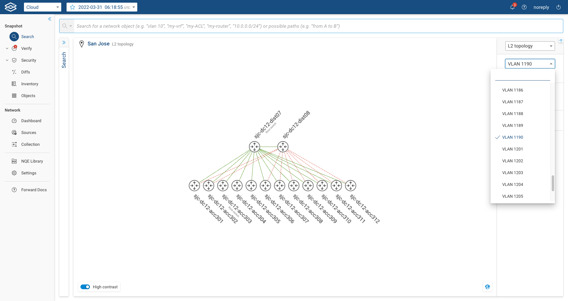
The default view for the location topology is based on physical links (+ tunnels). To see the Layer2 view of a location, the user can go to the selected location and, on the right panel, select "L2 Topology":
When the user selects the L2 Topology, the system will display only devices that have Layer2 links and only their Layer2 interfaces (Layer3 interfaces are not displayed). By default, the system displays interfaces carrying VLAN 1. The user can change the default VLAN and select the VLAN of interest on the right panel:
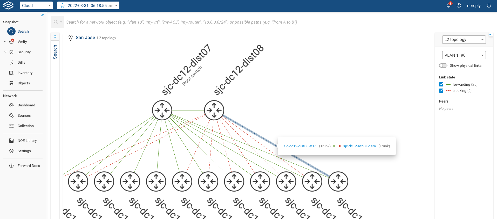
The system shows the links that are in STP forwarding state with green lines and those in blocking state with a dotted red line. By clicking over the blocked link, the user can see which of the ports is actually in blocking mode. Additionally, the system labels the Root Switch for the selected vlan.
Layer 3 topology layer
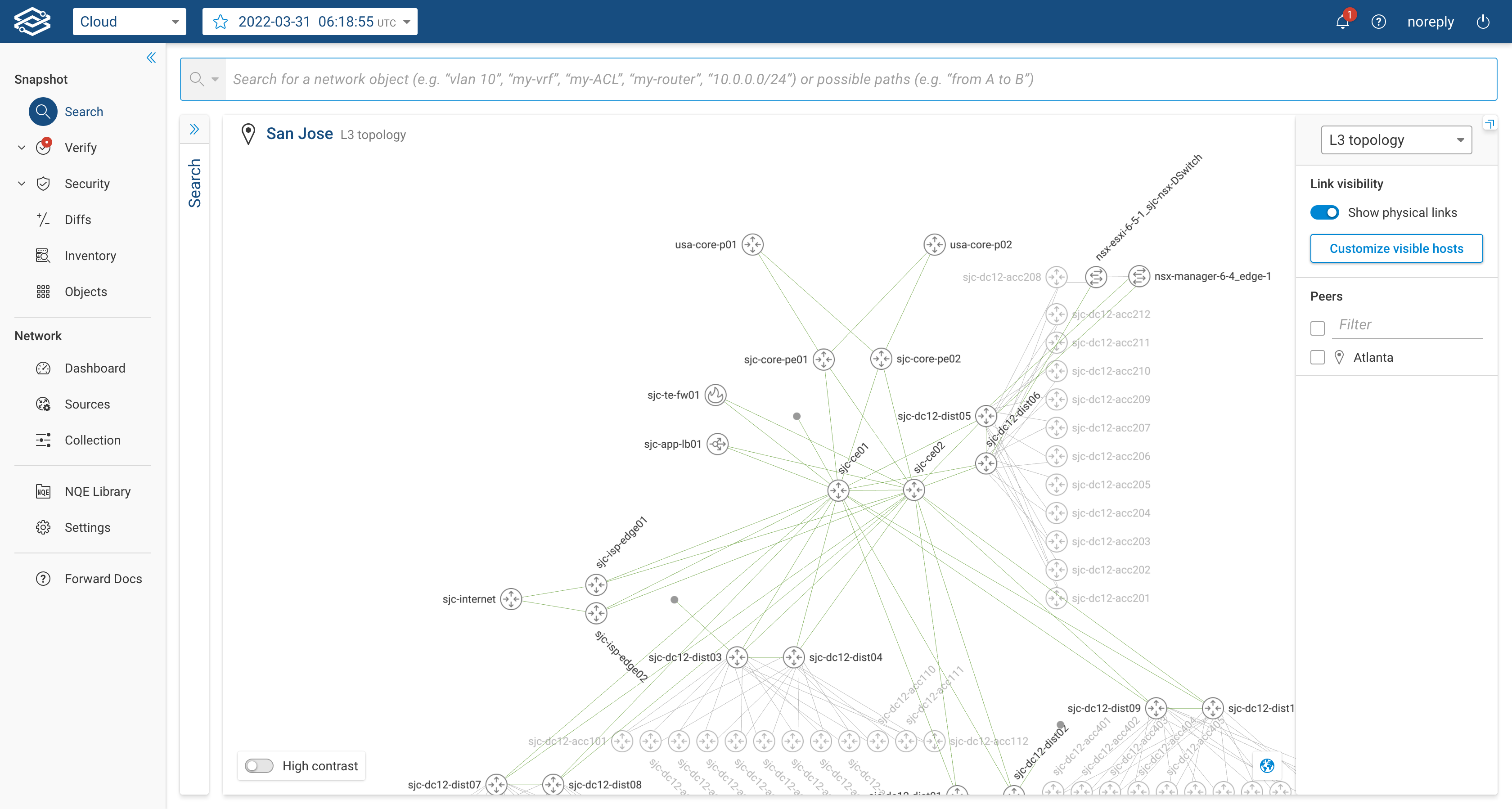
To see the Layer 3 view, go to the selected location and, on the right panel, select "L3 Topology":
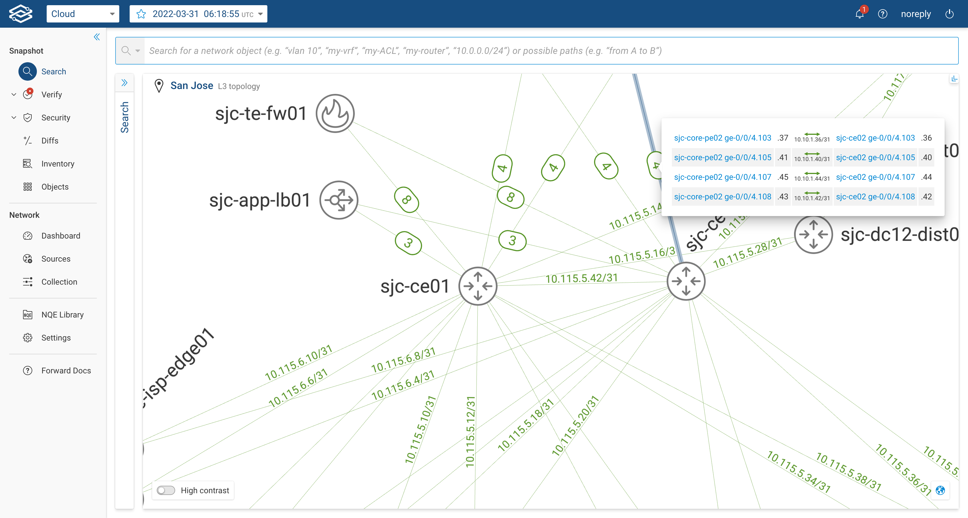
When the user selects the Layer 3 Topology, the system will display only L3-enabled devices and their layer 3 interfaces (i.e. pure layer 2 switches won't be displayed). The displayed layer 3 links will be accompanied by the IP Subnet of the layer 3 interfaces forming the link. If multiple layer 3 links are present between two devices, the system will display a single link carrying an encircled number; the number represents how many layer 3 links are actually present between the two devices. By clicking on the encircled number, the user can see the list of interfaces and subnets of each link. The image below shows an example:
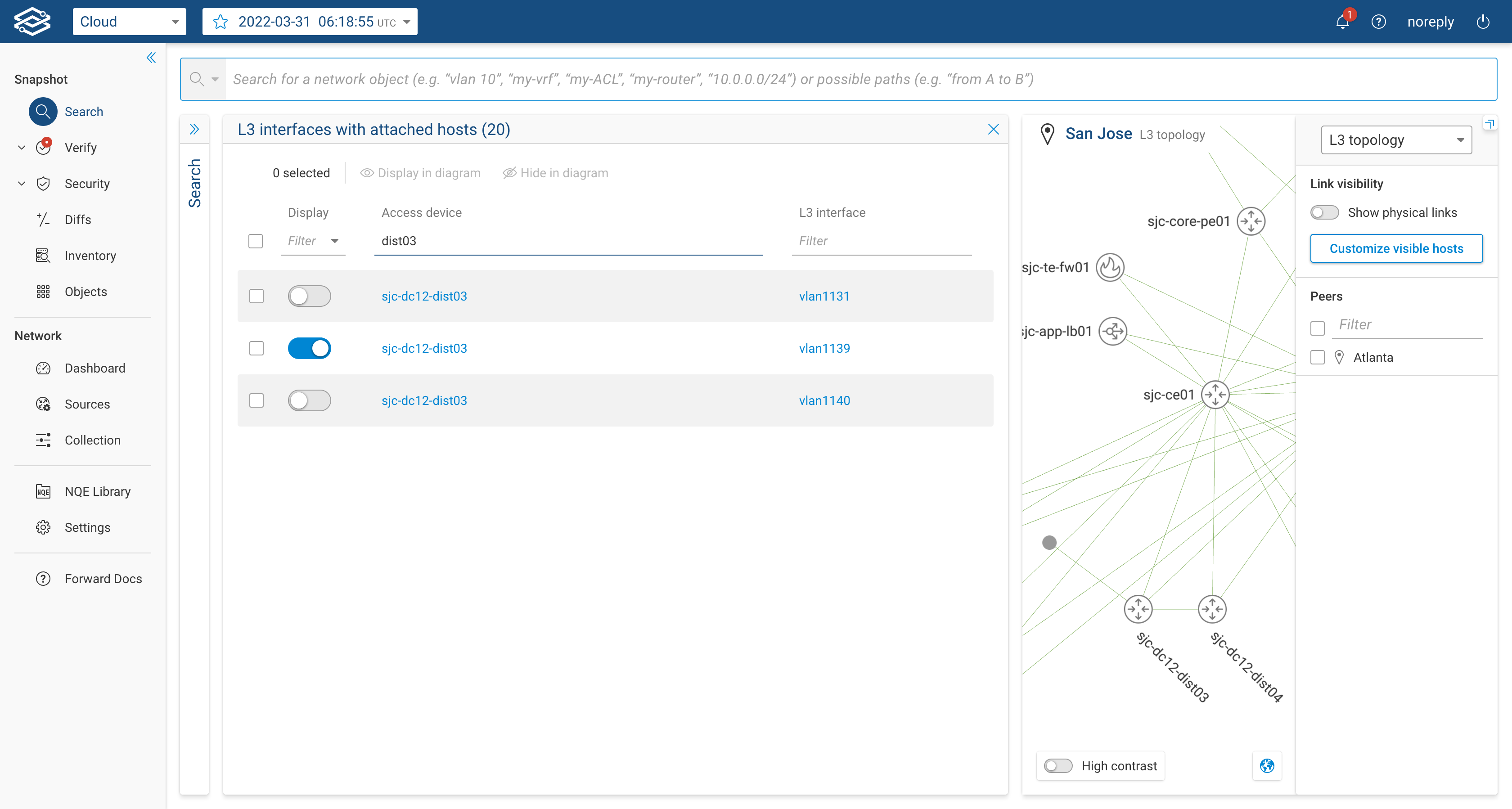
The user can customize the layout by adding layer 3 links to hosts, these links are not displayed by default as they can easily overwhelm the layout. The users can click on "Customize visible hosts", filter by device and select the layer 3 interfaces for which they want the host icon to appear.
By clicking on the host icon, the table with the attached layer 3 host will be shown:
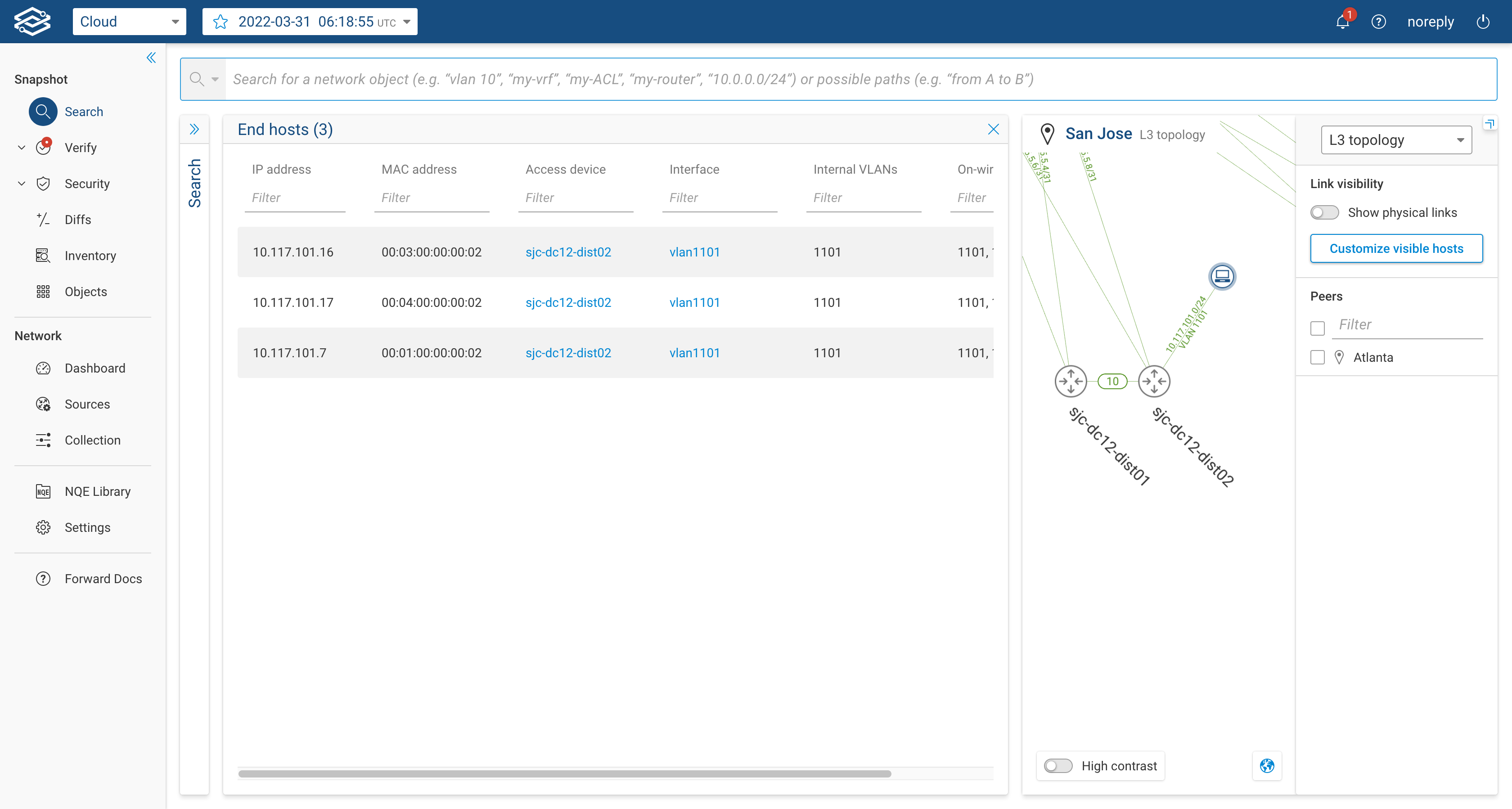
The user can also decide to display the physical links by clicking on the button on the right panel.
BGP topology layer
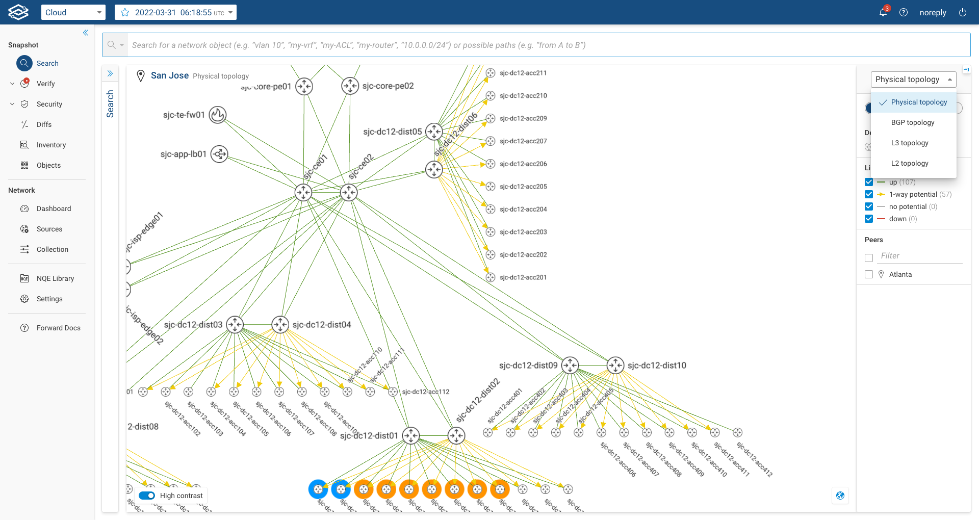
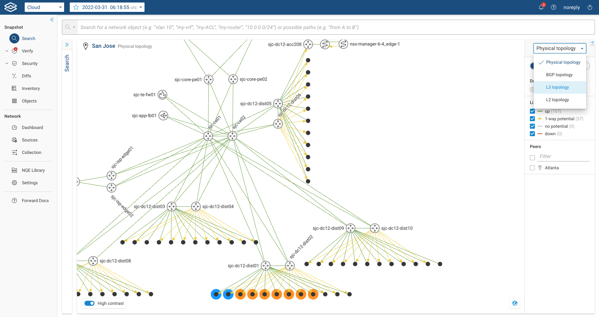
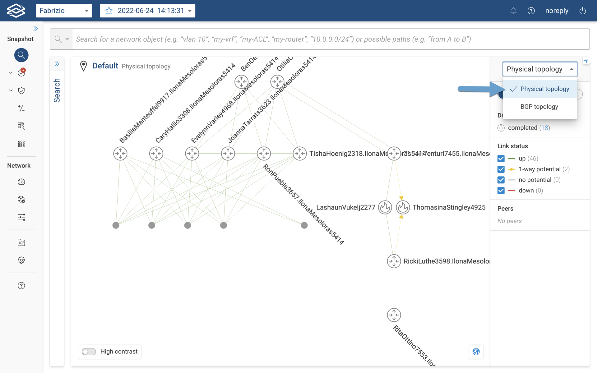
In order to view BGP topology, the user will not need to configure any additional steps within the Forward Enterprise platform. When the user navigates to the Search application, the default topology view will be Physical Topology . However, the user now has an option to switch the view from Physical topology to BGP topology as shown in the image below.
When the user selects the BGP topology view, the topology diagram will show relevant device and its connectivity as seen in the image below.
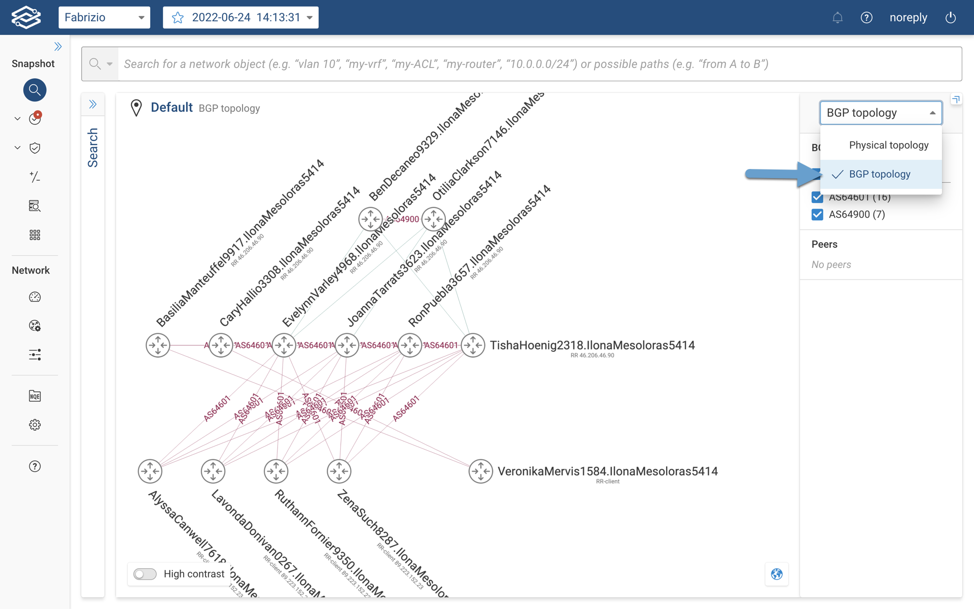
At a glance, the BGP topology layer provides following important information:
- AS number in which the device belongs to.
- BGP connection type (i.e. iBGP or eBGP).
- Role of the BGP speaker (i.e. Route Reflector, Route Reflector - Client, Independent if not specifically mentioned)
- BGP router ID.
Users also have the ability to filter the view by AS numbers. If the current location extends its BGP connectivity to other peer locations, the list of the locations will be available in the side panel for filtering purpose.
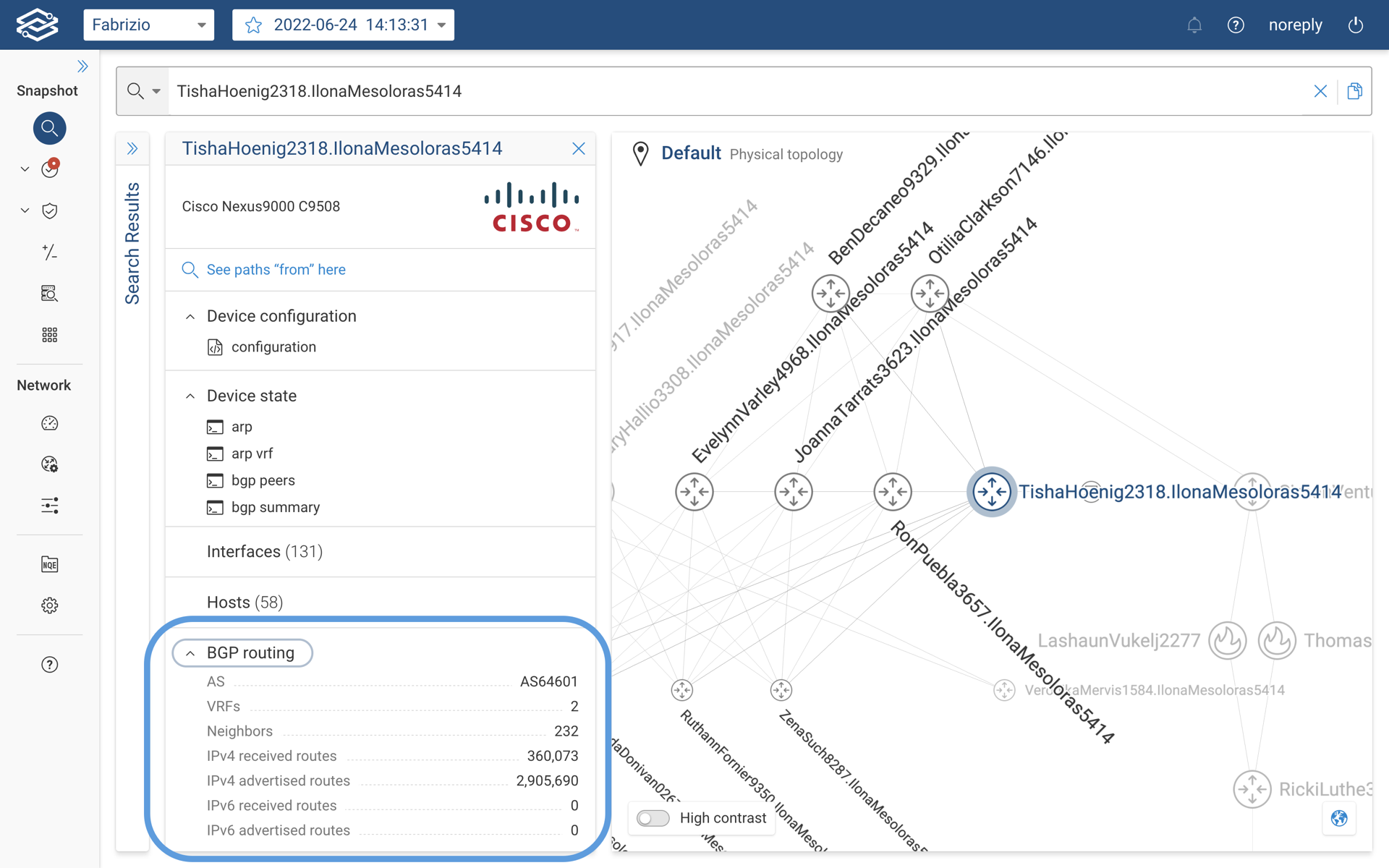
To discover more details about a specific BGP speaker, user can click on the device which provides the basic information.
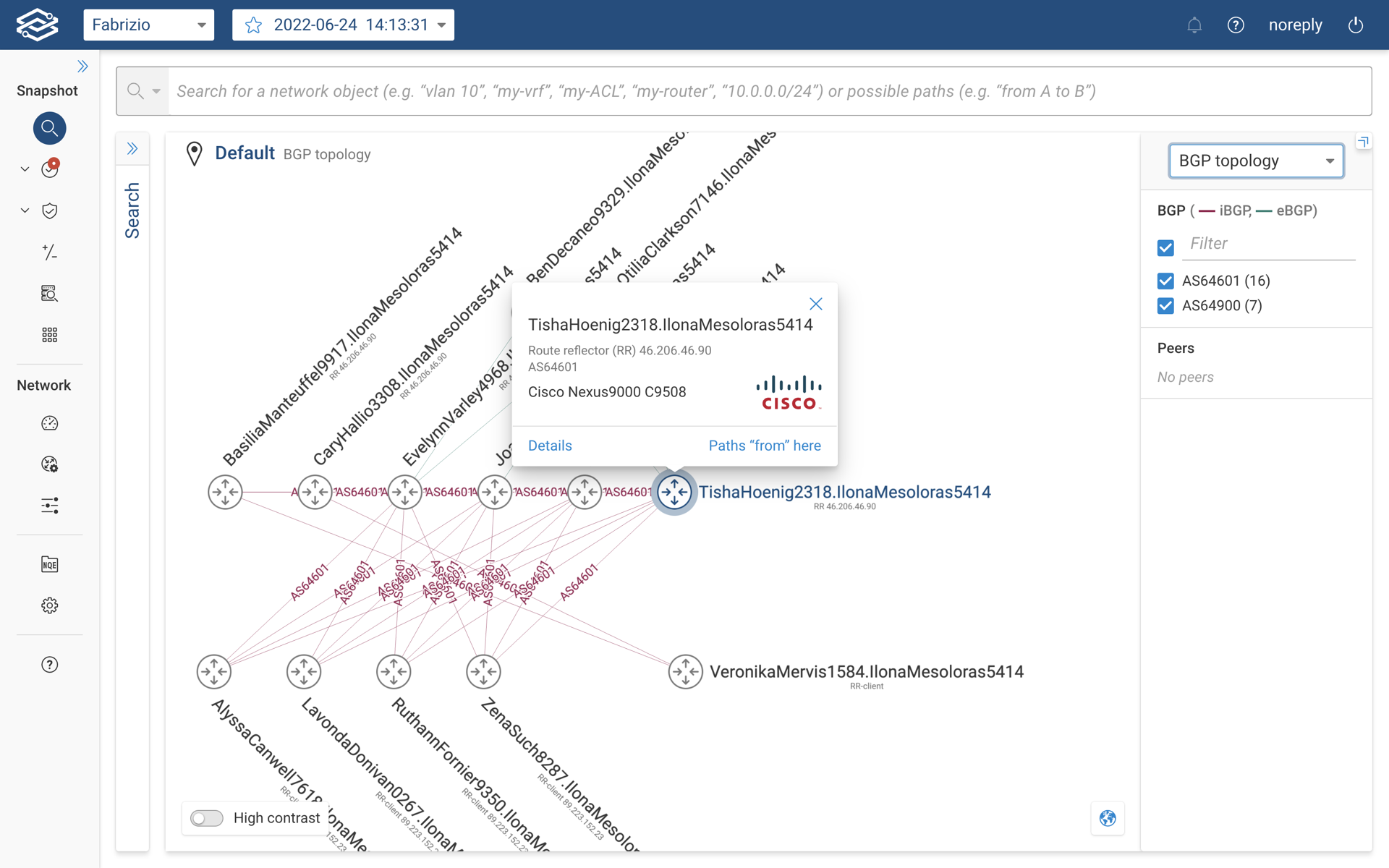
A high level overview of BGP speaker is available under the device details card as shown below.
OSPF topology layer (Tech Preview)
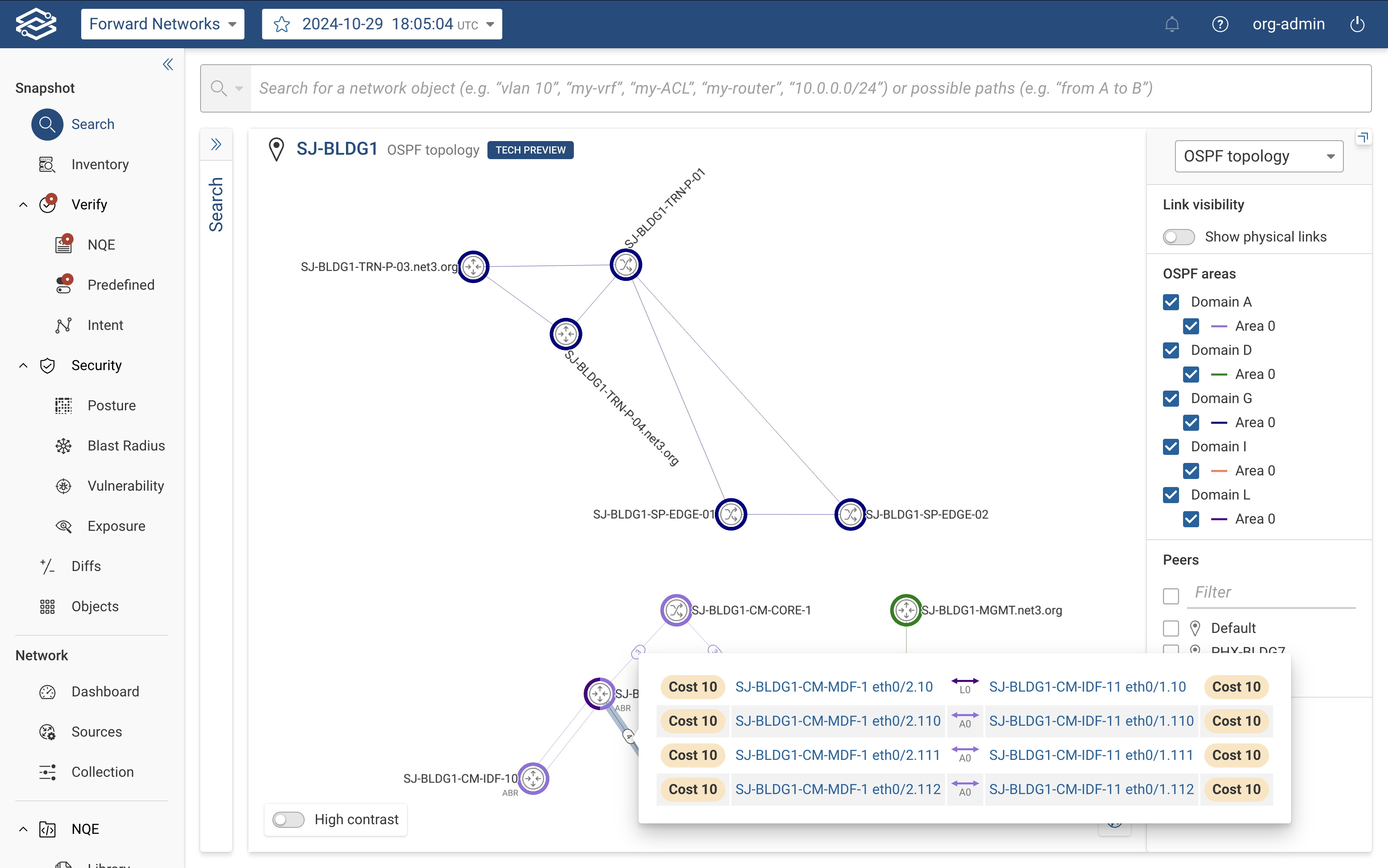
The OSPF Topology Layer provides users with a comprehensive view of OSPF (Open Shortest Path First) routing domains and areas within the Topology View of Forward Enterprise. This view provides insights into OSPF routes, link costs, and device participation across different OSPF areas within the selected network.
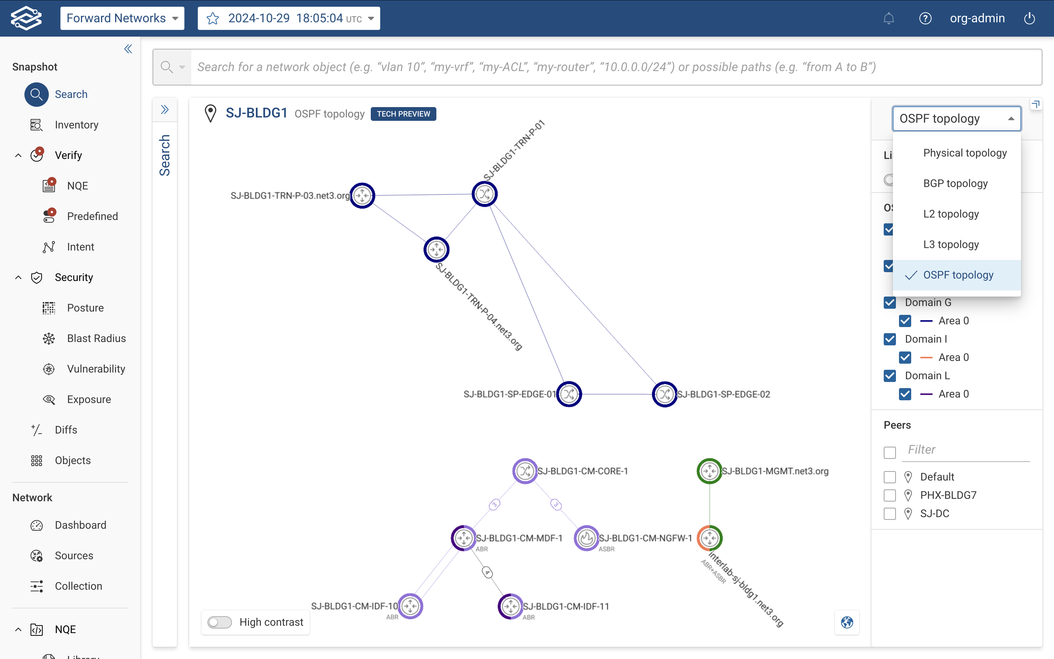
To view the OSPF topology of a selected network, select OSPF topology layer from the View Selector dropdown, located in the right-hand panel.
The right-hand side panel provides the following controls and insights:
- Link Visibility: Enable or disable this option to display physical links outside of the selected OSPF area(s).
- OSPF Areas: Displays all discovered OSPF areas, grouped by domain, with each area assigned a unique color. Devices
and links in the topology are color-coded to match their assigned area.
- Hovering over and clicking the Only button next to a domain filters the view to display only the selected domain or areas in the selected domain.
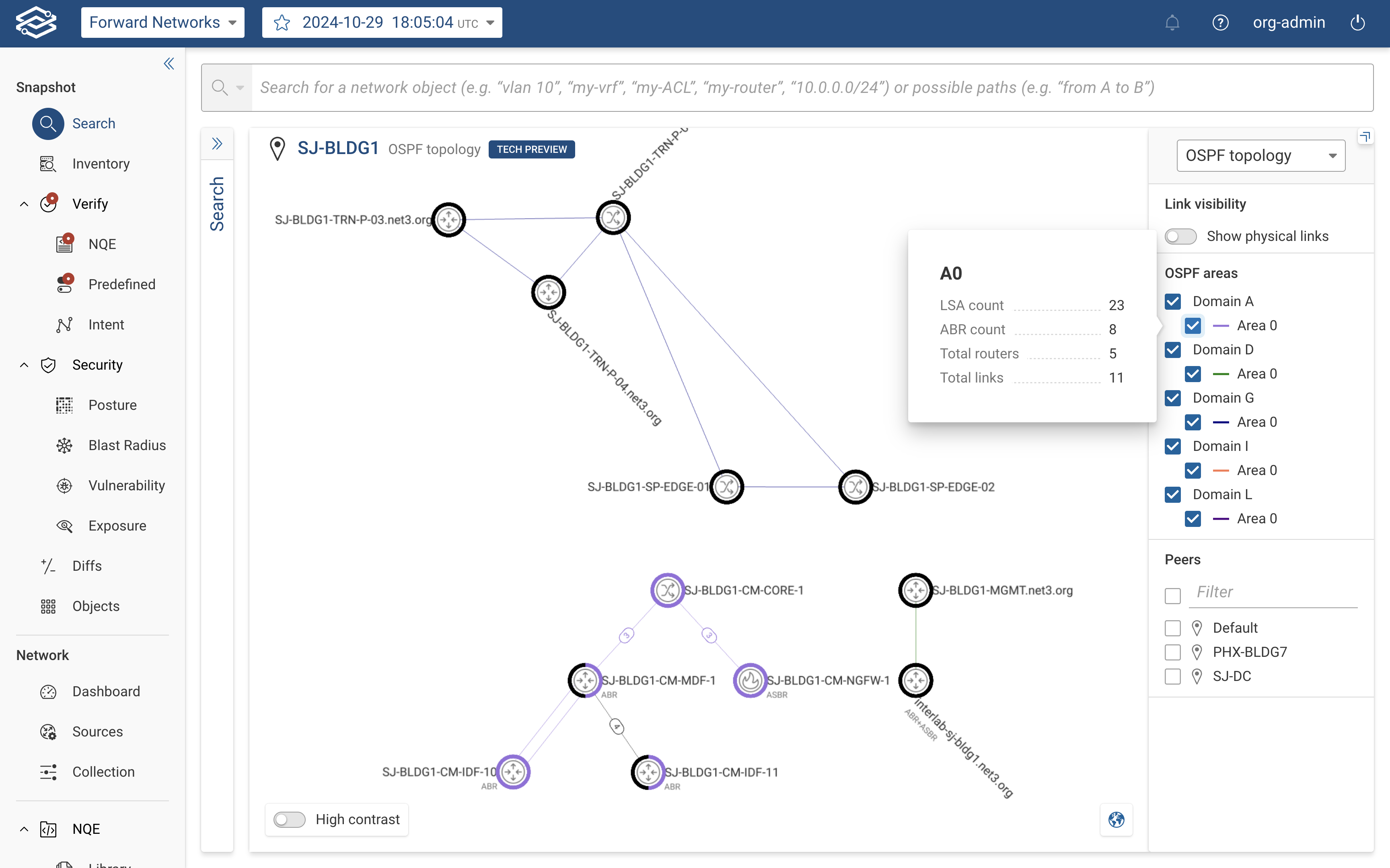
- Hovering over an area displays additional information, including:
- LSA count: Total number of Link-State Advertisements.
- ABR count: Number of Area Border Routers.
- Total Routers: Total number of routers in the area.
- Total Links: Total number of links within the area.
- Peers List: Displays a filtered list of peer locations for the selected OSPF topology.
The OSPF Topology Layer displays devices and links with color-coded indicators to represent their OSPF areas.
Device Nodes:
- Color-Coding: Devices are displayed with a halo around the node that matches their assigned OSPF area(s).
- Devices belonging to multiple OSPF areas:
- Devices in one to three areas: The halo displays up to three distinct colors.
- Devices in more than three areas: A rainbow halo is used for clarity.
- Devices belonging to multiple OSPF areas:
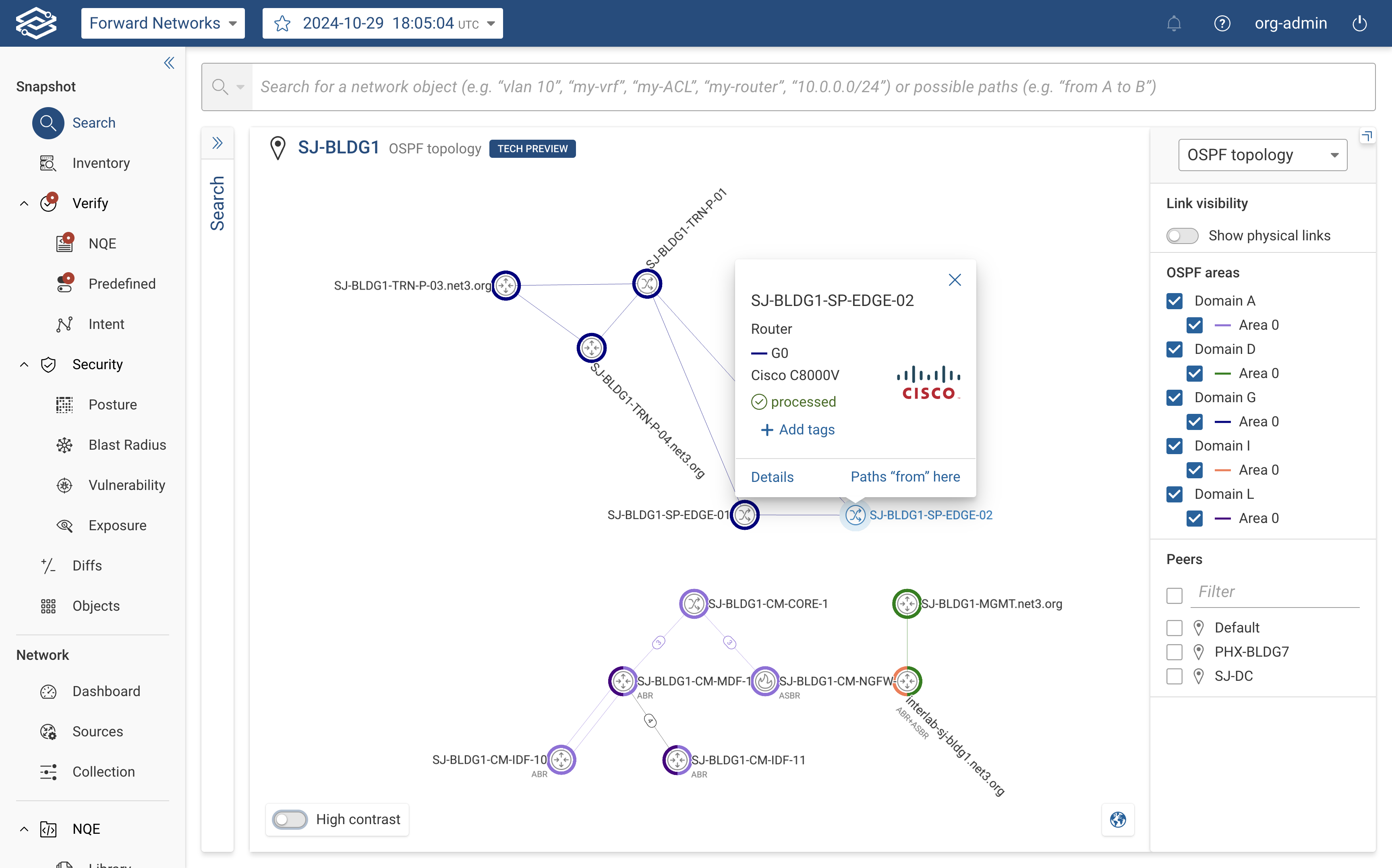
- Device Details: Clicking on a device displays:
- The assigned OSPF areas.
- Router Type: Identifies the device as:
- Area Border Router (ABR).
- Autonomous System Boundary Router (ASBR).
- Standard router participating in multiple areas.
Device Links:
- Color-Coding: Links between devices are color-coded to indicate their assigned OSPF areas.
- Link Details: Clicking a link displays the assigned OSPF area and the link cost.